


This Laptop motherboard repair guide gives you a repeatable, evidence‑based workflow from first intake to final QA. You will see how to set up a safe bench, choose tools that matter, build a fault‑finding plan, follow power rails in sequence, perform careful micro‑soldering, and decide when to escalate a job.

Mindset, safety, and workspace setup
Board repair rewards habits more than heroics. Clear notes, slower hands, and consistent checklists reduce rework and keep parts alive. The goal is not to guess faster, but to remove uncertainty step by step without creating new damage. Treat every board like it holds irreplaceable data and assume there is at least one surprise you have not found yet.
Safety starts with you and the device:
- ESD control: Work on a grounded mat and wear a wrist strap. Keep humidity reasonable to avoid sudden static discharge.
- Fumes and heat: Use a fume extractor and place hot tools in a safe stand. Shield plastics near heat zones with Kapton and aluminum foil where appropriate.
- Lighting and optics: Use adjustable lighting and either a stereo microscope or a sharp digital microscope for inspection and soldering.
- Organization: Lay out labeled parts trays, a screw map, and a notebook or digital log to record voltages, resistance readings, and actions in time order.
Make time for warm‑up passes. Before you touch a suspect area, practice a few joints on a scrap board to dial in air, temperature, and tip choice for the day. Calm hands plus known tool settings will save a connector, a pad, or an hour of cleanup more often than any one trick.
Laptop motherboard repair guide: orientation and board anatomy
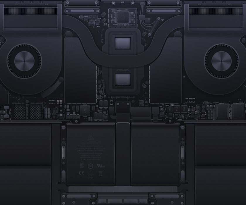
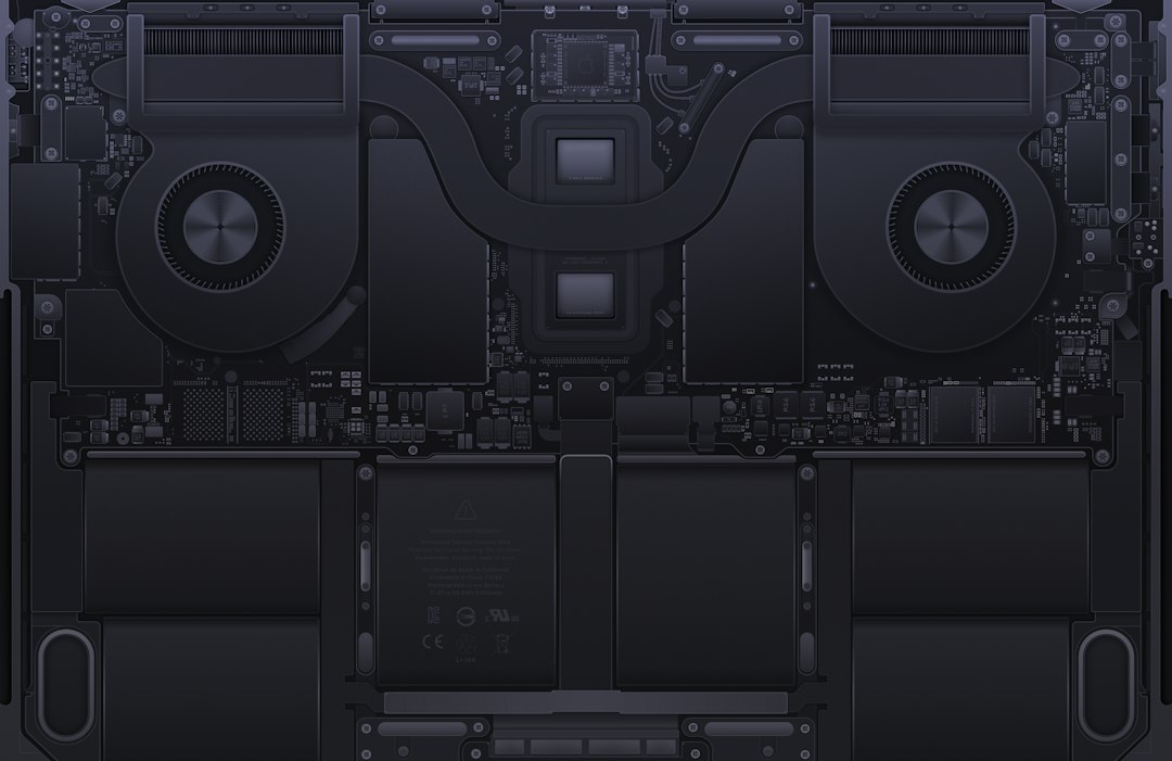
Before you measure anything, map the terrain. A modern laptop motherboard is a collection of power domains with strict sequencing: entry protection, charging and system rails, always‑on rails, wake logic, and high‑current cores. When you know where a rail should appear in the sequence and what should declare itself “good,” the chaos turns into a checklist.
Typical landmarks you will find on most platforms:
- DC‑in and protection: Barrel jack or USB‑C PD controller, input fuse, TVS diode, and back‑to‑back MOSFETs.
- Charger IC domain: A charger controller (often BQ‑series or similar), a current sense resistor, and charge FETs. Look for pins such as ACOK/PG that expose status.
- Always‑on low rails (3V/5V AUX): Feed the embedded controller, RTC, and housekeeping logic; they should be present early.
- Enable chain and power‑good: Signals that request the next rail (conceptually moving from S5 to S3 to S0 states); missing enables stall the entire bring‑up.
- High‑current cores: CPU/GPU VCORE, memory rails, and graphics rails driven by buck controllers with large inductors and MOSFETs.
- IO and peripherals: USB power switches, audio codec supply, Wi‑Fi module rails, NVMe/SATA power switches, and backlight drivers.
Even without a schematic you can trace major paths by component recognition and silk labels. Test pads near inductors often expose rail voltages and power‑good lines. If you do have a schematic and a boardview file, confirm net names, locate the best measurement points, and mark a simple sequence diagram before you probe.
Tools and test gear that pay for themselves
You can accomplish real work with a focused kit that grows as cases get tougher. Start with reliable basics and add selectively.
- Multimeter: Fast continuity beep, stable auto‑range, needle probes, and micro‑grabbers for dense areas.
- Bench power supply: Adjustable voltage with current limit for gentle power injection on shorted rails.
- Thermal camera or alcohol test: A camera speeds short‑hunts; absent that, isopropyl alcohol or freeze spray reveals the first warming part under injection.
- Hot‑air station and preheater: Tunable airflow and temperature; a preheater reduces thermal shock and helps large boards flow predictably.
- Soldering iron: Fine tips, tip cleaner, quality leaded solder for rework, a reliable flux, and solder wick.
- Microscope: 3–10× stereo or a high‑quality digital scope; both help you read laser‑etched IC marks and inspect pads.
- Consumables: Kapton tape, foil shields, isopropyl alcohol, ESD brushes, cotton swabs, low‑melt alloys when appropriate.
- Data protection: NVMe/SATA enclosures and external storage for quick imaging or targeted backups before risky work.
Useful extras include a USB‑C PD trigger or analyzer, debug cards for certain platforms, and an ultrasonic cleaner with electronics‑safe solution. The secret is not owning every tool; it is knowing which one settles the question in front of you with the least risk.
Schematics, boardview, and documentation workflow
Documentation is your second set of eyes. A schematic tells you intended rail names, reference designators, and signal relationships; a boardview maps those nets to physical pads and test points. Working without them is possible, but slower.
A practical workflow:
- Open the schematic and boardview side by side. Search for DC‑in, charger IC, AUX rails, and each buck controller. Bookmark enable and power‑good pins.
- Create a bring‑up checklist in your notes: DC‑in present → charger OK → 3V_AUX present → EC awake → 5V_AUX present → next enables.
- For a dead rail, trace the enable path backward. If the enable is low, find who drives it and why it may be withheld. If enable is present but output is missing, test input voltage, switching node, and downstream shorts.
- Document each reading with the exact test location. If a job returns months later, those points become your shortcut.
When you cannot find documentation, build your own “micro schematic” for the affected domain: draw the charger or buck controller pins you can see, label the large inductor node, and note any power‑good pad you identify. That minimal map keeps you from circling the same cul‑de‑sac.
From symptom to hypothesis: a fault‑finding framework
Clarity at intake speeds the entire repair. Translate vague descriptions into crisp behaviors. “Dead, no lights” is not the same as “charge LED on, no power button response,” and “fans spin once then stop” differs from “fans run but no video.” Each one places you at a different mile marker in the sequence.
Build a loop you run on every board:
- Interview and visual pass: Confirm the history, inspect for bent pins, missing screws, deformed shields, and corrosion near common spill zones.
- Baseline meter checks: With the battery disconnected, confirm DC‑in at the board, measure resistance to ground through big inductors for main rails, and note anything suspiciously low.
- Sequence test: Verify presence of always‑on rails. If they are missing, you are in the entry or charger stage. If present, check whether the EC wakes and asserts enables for the next rails.
- Behavior under the button: Does current draw blip and drop when you press power? Does it pulse in a repeating pattern? Those time‑domain clues often point to a failing rail’s power‑good.
Convert each observation into a small hypothesis and test that first. If 3V_AUX is present but 5V_AUX is missing, do not jump to the CPU; inspect the 5V buck’s enable, input, and switching. Evidence, not hunches, should decide where you go next.
No power cases and the power path
When the machine is truly dead—no LED, no fan twitch—start at the beginning and walk forward.
- Adapter and jack: Confirm the adapter under load. Wiggle the barrel or USB‑C plug gently to expose intermittent contacts. For USB‑C, use a PD trigger to see if the board asks for more than 5 V.
- Protection MOSFETs: Measure source and gate. If the back‑to‑back pair does not open, check the charger’s AC present and gate drive logic.
- Charger controller: Look for its internal regulator and status pins. A cracked current sense resistor can leave the system running on adapter but unable to charge, or it can block both directions.
- Always‑on rails: If 3V_AUX is missing, check its buck controller’s enable and input voltage. If 3V_AUX is present but nothing responds, the EC may be held in reset or missing its reference clock.
For early hard shorts, lift a coil to split the rail and inject power to the downstream half with a low, safe voltage. Use a thermal camera or the alcohol test to find the first component warming. Once you see a part heat up, pause and confirm it is actually on the shorted net, not a neighbor warmed by conduction. Removing a small ceramic capacitor can clear a short that looks catastrophic.
Power‑on attempts, fan spin, no display
Power button responses with no video suggest that some rails come up but not all of them remain healthy. Here your best tools are the schematic’s rail timing chart, a meter, and, if available, a scope.
- Memory and core rails: Confirm that CPU core, memory, and system agent rails appear in order and stay stable. If a rail sags then recovers in a loop, the EC may be retrying a failed enable.
- Internal vs. external display: Test an external monitor. If the external port works but the internal LCD is dark, suspect the eDP cable, LCD power, or backlight. If both are dark, look earlier in the chain.
- Firmware health: If the platform stores BIOS/UEFI in an SPI flash, a corrupted image can mimic hardware faults. If you have the skills and tools, make a backup of the original, program a known‑good image matched to the model’s configuration, and retest.
- Thermal protection: Remove and reseat the heatsink if the machine shuts down early. Bad paste contact or an unplugged fan can trip thermal safeties before video.
Current draw behavior helps: a steady low draw that never ramps often points to a missing enable; a rising draw that falls when a rail fails power‑good suggests the culprit is just downstream of that point in the chain.
Charging faults and battery issues
“Plugged in, not charging,” “battery not detected,” and “charges to 60% then stops” each lean toward different links in the same path.
- Adapter detect and status: On many chargers, pins like ACOK reveal whether the adapter is recognized. If recognition fails, check the AC detect divider and the PD controller on USB‑C systems.
- Charge path integrity: Inspect the current sense resistor for hairline cracks and confirm the charge FETs switch as commanded. The system rail may work while the pack never receives current.
- Battery communications: SMBus/PMBus lines require intact pull‑ups and good continuity to the EC or charger. Corrosion in or near the battery connector is common after spills.
- Pack health: A worn or locked pack can confuse the system. When safe and available, test with a known‑good compatible pack to isolate board versus battery questions.
On USB‑C, broken CC pins or a failed PD controller stops negotiation for higher voltage/current, leading to stubborn 5 V behavior. A PD analyzer or trigger confirms what the board requests and what the adapter offers.
Liquid damage workflow
Liquid creates both immediate shorts and long‑term corrosion. Your job is to end the chemical reaction, remove residue, and restore compromised connections without spreading contaminants into clean areas.
Effective steps:
- Disconnect all power first—charger and battery—then avoid powering on until the board is cleaned and dried.
- Disassemble fully: remove the board, flex cables, speakers, and storage. Note any spread pathways, such as trackpad flexes or screw posts.
- Pre‑clean with high‑purity isopropyl and soft ESD brushes. Work from the cleanest edge inward and blot, do not smear.
- Inspect under the microscope for green/black residue, lifted pads, and compromised connectors, especially near the keyboard, trackpad, DC‑in area, and audio codec.
- Use an ultrasonic cleaner with electronics‑safe solution if appropriate for the contamination level. Dry thoroughly with low heat and ample time; look for moisture trapped under shields.
- Replace corroded FPC connectors and any passives whose pads look undercut. Expect damage under chips where capillary action pulled liquid, and be ready for follow‑up work after the board stabilizes.
Make data decisions early in spill jobs. If the storage is removable and readable, image it before extensive heat work. That reduces stress for everyone if the board later resists further repair.
Shorts and heat hunts: systematic isolation
Shorts are common and intimidating only until you break the problem into smaller searches. Resist the urge to carpet‑remove capacitors. Divide and measure.
- Measure resistance through inductors: Record resistance to ground on each major rail. Sub‑ohm readings on logic rails often indicate a short; a few ohms may be normal on core rails.
- Divide the net: Lift a coil or remove an accessible power switch to split a rail into sections. Re‑measure each side to see which half holds the short.
- Inject power safely: With a current‑limited PSU, inject a low voltage appropriate for the rail and watch for heat. Start low and creep up; many faults reveal themselves well below nominal voltage.
- Verify target parts: Confirm the heating component is electrically on the shorted net. A neighbor IC can warm by conduction and lead you astray.
Common culprits include shorted ceramic capacitors, failed USB power switches, damaged ESD diodes, and occasionally ICs with internal failure. If the hot spot is a large BGA, weigh the next steps carefully. Board warpage, underfill, and hidden damage can reduce the odds of a lasting result with minimal tools. Partnering with a specialist lab for advanced BGA work can be the most conservative choice for the device and the data.
Micro‑soldering, connectors, and pads
Connector repairs are frequent, satisfying, and a great way to build confidence. The trick is control: heat, alignment, and anchoring pads or micro‑wires cleanly.
- DC‑in and USB‑C ports: Reinforce the board, wick old solder, preheat, and reflow evenly. Anchor posts must wet properly before you commit to final alignment.
- FPC connectors: Mask nearby plastics, align with gentle pressure, and reflow with even heat. Avoid prying when hot; let the joint cool before testing anchoring strength.
- Pad repairs: If a pad lifts, tin a hair‑fine wire from the device pin to the nearest exposed via on the same net. Verify continuity and strain‑relieve the wire before final assembly.
- Passive swaps: Match size, value, and voltage rating. For power circuits, pay attention to ESR and ripple specs where they matter, especially on buck output capacitors.
Keep the iron tip clean, use flux purposefully, and confirm joints under magnification. Building muscle memory on scrap boards pays dividends when the real job is under the microscope.
Firmware, EC, SPI flash, and platform locks
Firmware issues can masquerade as hardware failures. Embedded controllers and PCH/SoC firmware participate in the power sequence, and quirks here can stall an otherwise healthy board.
- SPI flash handling: Identify the correct SPI chip and back up the original contents before doing anything else. Work with verified images matched to the model, including correct descriptor and management engine regions where applicable.
- EC behavior: The EC needs stable AUX rails and proper reset conditions. If the EC never asserts the next enable, investigate its power, clock source, and the state of lid/thermal/keyboard inputs.
- Platform ties: Some devices tie encryption or platform identity to the original board. Plan data steps carefully and communicate limits if the owner expects a swap to “just work.”
Be patient around firmware questions. A single bad bit in an SPI image can waste hours elsewhere. Keeping a record of known‑good images and programmers you trust helps you avoid repeated paths.
USB‑C PD, adapters, and cable pitfalls
USB‑C laptops add a negotiation layer, and fault‑finding is easier once you can see who is asking for what. Many “dead” USB‑C laptops simply sit at 5 V because CC lines cannot establish identity or the PD controller is unpowered.
- Use a PD trigger/analyzer: Confirm whether the board requests 9/15/20 V profiles. If it never moves beyond 5 V, inspect CC pins, the PD controller, and its supply rail.
- Test multiple known‑good cables and adapters: E‑marked cables, passive cables, and low‑power phone chargers behave differently. An adapter that charges a tablet may not supply the negotiated power a laptop expects.
- Observe current draw changes: On a working system, current should jump when the board accepts a higher‑voltage profile. Flat behavior suggests negotiation never completes.
Document USB‑C behavior in your intake notes. It prevents chasing ghosts caused by a weak adapter and gives you a quick comparison after a repair step.
Reassembly, verification, and QA checklists
Stability and peripheral function matter as much as power‑on. A methodical QA pass protects you from near‑misses and awkward callbacks.
- Reassembly habits: Replace thermal paste and pads, route cables as the factory did, install correct screw lengths, and inspect standoffs and shields for missing insulators.
- Smoke test: Power on with the minimal set first—board, RAM, keyboard, and one storage device. Watch current and behavior before adding the rest.
- Thermals and stress: Run a controlled load and observe temperature curves, fan ramp, and throttling behavior. Confirm both fans spin where dual fans exist.
- Peripheral checks: Test USB ports, audio, camera, Wi‑Fi, Bluetooth, keyboard backlight, card reader, and sleep/wake behavior; backlight brightness should respond smoothly.
- Battery run check: Verify a brief discharge and recharge. Confirm the pack reports sensible capacity and cycle information where available.
Record your final readings and any replaced parts in the job ticket. Good notes help you support the repair and refine your process over time.
Data‑first thinking and customer communication
Boards are replaceable more often than data. If the storage is removable and readable, take an image or a targeted backup before you apply extended heat or riskier steps. If storage is soldered, stabilize power and IO enough to attempt a logical backup, then reassess the board work.
Communicate clearly about unknowns, decision points, and risks. Explain that you work in increments, stop if a risk grows out of proportion to the value of the machine or its data, and that some outcomes require referral or parts sourcing that changes the plan. For general hardware tips and local help, you can browse additional notes on our site at yourcomputerinc.com, where related guides and checklists live under Hardware Repair Tips.
When to stop, escalate, or refer
Knowing your limits protects both the device and your schedule. Pause or refer when:
- The suspected fault lies inside a large BGA with no reliable replacement path and limited tooling on hand.
- Layer damage from severe liquid exposure suggests hidden breaks in buried traces or vias.
- Essential documentation is unavailable and blind probing risks compounding damage.
- Data priorities outweigh further board work, and a specialist data lab offers better odds.
Share your notes—voltages, resistance readings, rail order, and behaviors—so the next technician can continue without repeating earlier steps. Referrals done well build trust both ways.
Common faults by symptom (quick reference)
Use this short list as a triage compass. Each line is a clue, not a verdict; confirm with measurements.
- No lights at all: DC‑in jack or USB‑C PD path, input fuse, back‑to‑back FETs, charger status pins, or a direct short on 3V/5V_AUX.
- Charge LED on, no power button response: EC held in reset, missing keyboard/sideboard signals, 3V_AUX present while the next enable is missing.
- Fans pulse repeatedly: A rail fails power‑good. Inspect enables and look for a marginal short that heats under load.
- Shuts off after 30–60 seconds: Heatsink pressure or paste issue, fan unplugged, or a core rail that goes unstable under load.
- External display works, internal does not: eDP cable, LCD VDD/backlight driver, or panel damage.
- Erratic keyboard/trackpad after spill: FPC connector corrosion or the controller IC on that flex.
- Runs on adapter, will not charge: Sense resistor or charge FET failure, SMBus pull‑ups open, or a worn pack.
Field service essentials
Not every job starts at a full bench. When you must make an initial call on site, a trimmed kit can answer the most important questions and decide whether the device should travel back to the lab.
H3 mini‑checklist: packing your mobile kit
- Compact multimeter with fine probes and micro‑grabbers
- USB‑C PD trigger plus a couple of known‑good cables
- Basic temperature‑controlled iron, flux, wick, and a small tip kit
- Portable digital microscope or a strong illuminated loupe
- Small hot‑air station only if you expect connector work
- Kapton tape, tweezers, ESD pouches, isopropyl alcohol, and a mini tray
Even this light kit can establish whether power sequencing starts, whether the adapter path works, and whether the machine should be escalated to the full bench.
Maintenance, calibration, and shop routines
Stable results come from stable tools. Plan short recurring tasks so the bench meets you halfway every morning.
- Tip and nozzle care: Clean iron tips between joints, tin before shutdown, and replace tips that no longer wet properly. Keep hot‑air nozzles clear of flux buildup.
- Calibration moments: Verify your multimeter against a known reference periodically. Check that the bench PSU’s current limit behaves as expected at low voltages.
- Thermal profiles: Record the temperatures and airflow settings that work for common jobs on scrap boards. Those notes become your starting points for similar plastics and copper weights.
- Parts bins and labeling: Maintain labeled drawers for common passives, MOSFETs, USB power switches, and connectors you replace frequently. A 10‑minute search costs more than the part.
- Cleaning and ESD discipline: Wipe the mat, brush away dust that traps heat or hides shorts, and confirm your ground path with a quick meter check.
- Knowledge base: Keep a shop wiki with model‑specific quirks, rail names, and photos of test pads. Your future self will thank you.
Small routines add up to fewer mistakes, faster confidence, and calmer decision‑making when a tricky board lands on the mat late in the day.
Closing notes: build a repeatable practice
Successful board repair is a practice built from hundreds of measured moves. Set up a clean bench. Protect the board and the data. Follow a consistent sequence from DC‑in to AUX rails to core domains. Document what you see, and let evidence choose the next step. Handle micro‑soldering deliberately, and refer high‑risk BGA work when the device or data calls for it. Over time your notes become a field guide, and your calm process becomes the most valuable tool on your bench.